Thursday, 28 February 2013

உணர்ச்சி வழி

 கணவனால் அடிக்கப்பட்டு அல்லது உதைக்கப்பட்டு மனைவி வந்து நிற்பார்.பலரும் சொல்வார்கள்."அடிக்கிற கைதான் அணைக்கும்".வேறு போக்கிடம் ஏது? கொஞ்ச நேரத்தில் வீட்டுக்குப்போய் கணவனுக்கு உணவு சமைக்க ஆரம்பித்துவிடுவார்.அப்புறம் தம்பதிகள் சந்தோஷமாக இருப்பார்கள்.இன்னொரு நண்பர் வேறு விளக்கம் கொடுத்தார்.குழ்ந்தை ஓயாமல் தொல்லை செய்தால் தாய் அடித்து விடுவார்.சற்று நேரம் கழித்து வாரி அணைத்து கொஞ்சுவார்.இதெல்லாம் நாம் பார்த்துக் கொண்டிருப்பவைதான்.
அடிப்பதற்கும் சரி அணைப்பதற்கும் சரி மனம் உணர்ச்சியால் நிரம்பியிருக்க வேண்டும்.சிந்தனை தவிர்த்து உணர்ச்சி வழி நடக்கும் மனிதர்களை  நாம் நிறைய பார்த்துக் கொண்டிருக்கிறோம்.பக்கத்து வீட்டுக்காரர்களுடன் ஒருவருக்கு பெரிய சண்டை ஆகிவிட்டது.கெட்ட வார்த்தைகள்,கை கலப்பு என்று ஊர்  வேடிக்கை பார்த்தது.ஒரு மாதம் கூட ஆகவில்லை.இரண்டுபேரும் நண்பர்களாக சிரித்து பேச ஆரம்பித்து விட்டார்கள்.இருவரில் யாராவது ஒருவர் உணர்ச்சி சார்ந்து இருந்தால் போதும்.
இன்னொரு நிகழ்வு! பால்ய காலத்து நண்பர்கள் அவர்கள்.ஒருவர் இன்னொருவரைப் பற்றி தவறாக பேசியதாக நம்பகமான தகவல் கிடைத்தது.பேசுவதை குறைக்க ஆரம்பித்து பின்னர் முழுமையாக வெட்டிக்கொண்டு விட்டார்.அறுந்து விழுந்த உறவு விழுந்ததுதான்.பிறகு சேரவேயில்லை.
ஆளுமை உணர்ச்சி சார்ந்து இருப்பதற்கும்,அறிவு சார்ந்து இருப்பதற்குமான வித்தியாசம் இவை.இரண்டாவது நிகழ்வில் சிந்தித்து முடிவு செய்ததால் -நட்பு நன்மையைத் தராது என்று முடிவு செய்திருக்க வேண்டும்-பேசுவதைக் குறைத்து வெட்டிக் கொண்டுவிட்டார்.பெரிதாக சத்தம் போட்டு சண்டை ஆகவில்லை.ஆனால் சத்தம் போட்டு சண்டை போட்டவர்கள் உடனே சேர்ந்துவிடவும் செய்கிறார்கள்.
B.J.P என்று செல்லமாக அழைக்கப்படும் ஜொள்ளு பார்ட்டிகள் கிட்டத்தட்ட  இந்தவகைதான்.உணர்ச்சி வழி நடப்பவர்கள் உறுதியற்ற படகு போலத்தான்.கரை சேர முடியும் என்று உறுதியாக சொல்ல முடியாது.ஆனால் இவர்களை நம்புபவர்களே அதிகம்.அன்பு எனும் உணர்ச்சி தூக்கலாக இருக்கும்போது இவர்களைத் தவிர யாராலும் அத்தனை அன்பை பொழிய முடியாது.சோகமாக வந்து நின்று கெஞ்சுவார்கள்.முற்றிலும் சுயநலம் சார்ந்தது என்பது வேறு விஷயம்.அடிப்பதற்கும் அணைப்பதற்கும் தேவையானது மிகுதியான உணர்ச்சிதான்.நம்முடைய உறவினர்களையும் நண்பர்களையும் இவ்வாறே புரிந்து கொள்ளவும் முடியும்.எந்த வகை என்று தெரிந்துவிட்டால் உறவுகளை பேணுவது எளிது.

Friday, 15 February 2013

மனதை உற்சாகப்படுத்தும் உணவுகள்.


                              மனம் நல்ல நிலையில் இருப்பதற்கு உணவும் முக்கியமானது.அனைத்து சத்துக்களும் நிறைந்த உணவை தேர்ந்தெடுத்து உண்ணும்போது உடல் நலம் சிறப்பாக இருக்கும்.உடலும் மனமும் ஒன்றுக்கொன்று தொடர்புடையவை.ஜலதோஷம் பிடித்தால் கூட சிடுசிடுப்பும் எரிச்சலும் வந்து விடுகிறது.உடலில் ஏற்படும் நோய்கள் மனதையும் மனதில் ஏற்படும் நலக்குறைவு உடலையும் பாதிக்கும்.இந்திய மருத்துவத்தில் குறிப்பிட்ட உணவு உணர்ச்சிகளில் மாறுபாட்டை உண்டாக்கும் என்று சொல்வதுண்டு.

                               பெரும்பாலான வீடுகளில் நடக்கும் ஒரு நிகழ்வை கவனித்திருக்க முடியும்.நண்பர் ஒருவருக்கு அப்பாவுடன் சண்டை.காரசாரமான விவாதம் நடைபெற்று நண்பர் வெறுத்துப்போயிருந்தார்.அன்று மாலை அவருடைய அம்மா கடைக்குப்போய் திரும்பிக்கொண்டிருந்தார்.அவனுக்குப் பிடிக்கும் என்று பலகாரம் செய்யப்போகிறேன்.ஆமாம்.அம்மாவுக்கு தெரியாதா என்ன? குழந்தைகள் எதற்கு கவலையை மறப்பார்கள்? எப்படி வழிக்கு கொண்டு வருவதுஎன்பதெல்லாம் அவர்களுக்கு தெரியும்.ஒவ்வொருவருக்கும் சில உணவுகளில் விருப்பம் அதிகம்.விருப்பமான உணவுகள் மனதை சந்தோஷப்படுத்தி விடுகிறது.மனம் இறுக்கமாக இருக்கும்போது பிடித்த உணவை உண்பது இறுக்கத்தை குறைக்க உதவும்.

                               மேலே கண்ட அம்மா வைத்தியமும் இப்போது பெரும் சிக்கலை உண்டாக்கி வருகிறது.சிறுவயது முதலே இனிப்பு,குப்பை உணவு என்று பழக்கத்தை ஏற்படுத்துகிறார்கள்.அதிக எடை,ஆரோக்கிய குறைபாடு என்று திசை மாறிக்கொண்டிருக்கிறது.ஆரோக்கியம் தரும் பலகாரத்தை வீட்டில் செய்து தருவது இன்று சாத்தியமாக இல்லை.பொட்டலம் கட்டப்பட்ட அல்லது கடையை நம்பியே இருக்கிறார்கள்.அழும்போதெல்லாம் இப்படிப்பட்ட உணவுகளையே தின்னக் கொடுக்கிறார்கள்.இத்தகைய பழக்கங்கள் மருத்துவமனையை நோக்கி படையெடுக்க வேண்டிய அவசியத்தை ஏற்படுத்துகிறது.

                                                                       பெரும்பாலான வீடுகளில் இந்தப்பழக்கம் இருக்கிறது.சமைப்பதற்கு முன்னால் என்ன செய்யட்டும் என்று கேட்பார்கள்.ஆனால் அனைத்து உறுப்பினர்களையும் திருப்திப்படுத்துவது சாத்தியம் இல்லை.நமக்கு சில நேரங்களில் குறிப்பிட்ட உணவின் மீது ஆசை உண்டாகிறது.உணவின் மீதான ஆர்வத்துக்கும் உடல் நலனுக்கும் நெருங்கிய தொடர்பிருப்பதாக ஒரு கிராமத்துப்பெரியவர் சொன்னார்.உடலில் உள்ள நோய்க்கு தகுந்தவாறு உணவின் மீதான ஆசையும் இருக்கும் என்றார்.உதாரணமாக ஒருவர் உடலில் சி வைட்டமின் பற்றாக்குறையாக இருக்கும்போது சி உயிர்ச்சத்து மிகுந்த உணவுகளின் மீது ஆர்வம் உண்டாகும்.இது சிந்திக்கவேண்டிய விஷயமாகத்தோன்றுகிறது.
                                                                         மகிழ்ச்சி, நல்ல மனநிலை,தூக்கம் போன்றவற்றிற்கு செரோடானின் என்ற வேதிப்பொருள் முக்கிய காரணமாக உள்ளது.செரோடானின் அளவை உயர்த்தும் உணவுகளை உண்பது முக்கியமானது.வைட்டமின் பி சத்துள்ள உணவுகள்(பச்சை காய்கறிகள்,இறைச்சி,முட்டை,முளை கட்டிய தானியங்கள்,கைக்குத்தல் அரிசி,கோழி இறைச்சியின் மார்புப்பகுதி போன்றவை),வாழைப்பழம்,தக்காளி,அன்னாசி,கடல் உணவுகள் ஆகியவற்றை உணவில் சேர்ப்பது மகிழ்ச்சியான மனநிலையை தக்கவைக்கும்.

Friday, 8 February 2013

Basics of Transmission and Distribution Library


Basics of Transmission and Distribution Library

Introduction
       Components of Distribution
       Generators
       Transformers
       Transmission Line
       Bus Bars
       Circuit Breakers
       Isolators
       Effect of High Voltage on Volume of Copper
       Effect of High Voltage on Line Efficiency
       Effect of high Voltage on Line Drop
       Advantages of High Voltage Transmission
       Disadvantages of High Voltage
       Practical Transmission and Distribution Voltage Levels
       Overhead System
       Underground System
       Three Phase Three Wire System
       Three Phase Four Wire System
       Advantages of A.C. Systems
       Disadvantages of A.C. System
       Tow Wire D.C. System
       Two Wire D.C. System with Midpoint Earthed
       Three Wire D.C. System
       Advantages of D.C. System
       Disadvantages
       Tow Wire D.C. System With One Line Earthed
       Two Wire D.C. System With Midpoint Earthed
       Three Wire D.C. System
       Three Phase Three Wire A.C. System
       Three Phase Four Wire A.C. System
       Two Wire D.C. System
       Two Wire D.C. System With Midpoint Earthed
       Three Wire D.C. System
       Three Phase Three Wire A.C.System
       Three Phase Four Wire A.C. System

       Advantages of Radial System
       Disadvantages of Radial System
       Current Distribution in Three Wire D.C. System
       Concentrated Loads Fed at One End
       Concentrated Loads Fed at Both Ends
              Ends at Equal Voltages
              Ends at Unequal Voltages
       Distributor Load Fed at One End
       Distributed Load Fed at Both Ends
              Ends at Equal Voltages
              Ends at Unequal Voltages
       Power Factors Referred to Receiving End Voltage
       Power Factors Referred to Respective Load Voltages 

Methods of Solving A.C. Distribution Problems

       As discussed in earlier section of a.c. distribution system we have take into account the power factor. This power factor can be either considered with respect to receiving end voltage or with respect to load voltage itself. Let us consider each case separately.
1.1 Power Factors Referred to Receiving End Voltage 
       Consider an A.C. distribution PQ having concentrated loads of Iand Itapped off at point Q and R respectively. This is shown in the Fig. 1.
Fig. 1

        Let voltage Vwhich is the voltage at the receiving end be taken as reference vector. The power factors at R and Q are cosΦand cosΦwith respect to VQ and they are lagging.
Let,             R = Resistance of section PR
                  X= Reactance of section PR
                  R= Resistance of section RQ
                  X= Reactance of section RQ
       Impedance of section PR is given by,

       Impedance of section RQ is given by,

       The load current at point R is  Ī1,

       Similarly the load current at point Q is Ī2,

       The current in section RQ is nothing but Ī2,

       The current in section PR is given by,

       The voltage drop in section RQ is given by,

       The voltage drop in section PR is given by,

       Thus the sending end voltage Vis given as,

       The sending end current is given as,

       The corresponding phasor diagram is shown in the Fig. 2.
Fig. 2

       As shown in the Fig. 2. the receiving end voltage VQ is taken as reference vector. The currents  Iand Iare lagging from Vby angles of Φ1 and Φrespectively. The vector sum of Iand Igives current IPR. The drop is I2Rin phase with I while I2X2 is leading by 90o. The vector sum of VQI2R2 and I2Xgives VR. The drop  IPRR1 is in phase with current IPR while IPRX1  is leading by 90. The vector sum of VRIPRR1 and IPRX1 gives the sending end voltage.
1.2 Power Factors Referred to Respective Load Voltages
      In previous section we have considered the load power factors with respect to receiving end voltage. Here we will consider these power factors with respect to their respective load voltages. Now Φ1 is the phase angle between VR and Iwhile the angle Φ2 is the phase angle between V and I2.
       The phasor diagram under this condition will be as shown in the Fig. 3.
Fig. 3

       Here again the receiving end voltage VQ is the reference phasor. The vector sum of I1 and I2 gives the current IPR. The drop I2Ris in phase with Iwhile I2X2 is leading by 90. The vector sum of VQ, I2Rand I2Xgives voltage VR. The drop IPRR is in phase with current IPR while the drop IPRX1 is leading by 90o. The vector sum of VR, IPRRand IPRX1 gives the sending end voltage Vp.
       Now voltage drop in section RQ is given by,

...   The sending end voltage Vp is given by,

Read Solved Examples

Sunday, 3 February 2013

A.C. Distribution Calculations

      The A.C. distribution calculations and d.c. distribution calculations are different in the following respects :

1. In case of d.c. system, the voltage drop is due to resistance only which in a.c. system it is due to combined effect of resistance, inductance and capacitance.
2. The voltages or currents are added or subtracted arithmetically in case of d.c. system whereas they are added or subtracted vectorially in case of a.c. system.
3. It is required to take into account the power factor while making calculations in a.c. system which is absent in d.c. system. The distributors are normally tapped at different points with the loads having different power factors.
      There are two ways of referring the power factor.
a) The p.f. may be referred to receiving end voltage which is reference vector.
b) The p.f. may be referred to the voltage at load point itself.
       By different methods the a.c. distribution problems can be solved.
       The most convenient method is the symbolic notation method wherein voltages, currents and impedances are expressed in the complex notation and the calculations are similar to those in case of d.c. distribution. In a.c. calculations, addition and subtraction must be done by expressing various quantities in the rectangular form while the multiplication and the division must be done by expressing the various quantities in the polar from.

A.C. Distribution

       In earlier days, d.c. system was used for the generation, transmission and distribution of electrical energy. But in case of d.c. system the voltage level cannot be changed easily unless we used rotating machinery which may not prove to be economical in many cases. This is the major disadvantages while working with d.c.

       Later on with the development of transformer, a/c/ system has become predominant. Now days a large power systems in the world are using a.c. system rather than d.c. because of many advantages of a.c. system.
       The transmission of electrical energy generated in the power station is at very high voltage with the use of 3 phase, 3 wire system. These voltages are stepped down for distribution at the substations. There are mainly two parts of the distributor system. They are primary distribution and secondary distribution. The voltage level of primary distribution system is higher than general utilization level. The secondary distribution systems receive power from primary distribution systems through distribution transformers. By distribution transformer voltage is stepped down to the normal working level and the consumers get the power with the voltage 400/230 V. The very commonly used a.c. distribution system is three phase four wire system as studied earlier.

Ring Main Distributor With Interconnector

       It has been mentioned that in ring main system, the cable is arranged in the loop or ring fashion. In most simple case, the ring distributor is fed at only one point.

       But sometimes the ring main system is used to supply a large area and hence voltage drop across the various sections may become large in such case. Hence to compensate for such excessive voltage drops, the distant points of ring distributor are joined together by a conductor. This is called an interconnector. The Fig. 1 shows a ring main system with an interconnector.
Fig. 1

       The points D and G are joined by an interconnector.
       Such a case is generally analysed using Thevenin's theorem.
       Let us briefly revise the steps to use the Thevenin's theorem.
       The steps to use Thevenin's theorem :
1. Remove an interconnector DG.
2. Find the voltage VDG without an interconnector, which is Thevenin's voltage denoted as Eo.
3. Determine the equivalent resistance as viewed through the terminals D and G, i.e. where an interconnector is to be connected. This is Thevenin's equivalent resistance denoted as RTH.
4. Knowing the resistance of an interconnector DG, the Thevenin;s equivalent can be drawn as shown in the fed Fig. 2.
Fig. 2

5. The current I through an interconnector then can be obtained as,

       Once this current is known, current in all the sections and the voltages at load points can be determined.

D.C. Distributor With Distributed Load


       This type of distributor is also classified as,
1. Distributor fed at one end
2. Distributor fed at both the ends
1.1 Distributor Load Fed at One End
      The Fig. 1 shows the single line diagram of uniformly distributed load on two wire distributor, fed at one end.
Fig. 1

       Th Distributor load is of i amperes per meter.
       This indicates that at every metre length i amperes load is supplied through tapping on the distributor.
Let      l  = Length of the distributor
          r = Resistance per unit length in Ω
       In such case, total voltage drop is to be obtained by considering a point C at a distance x from feeding end A.
       This is shown in the Fig. 2.
Fig. 2

       The current tapped at point C is
              = Total current - Current up to point C
              = i x  l  - i x x
              = i (- x)
       Consider an elementary length dx near point C. Its resistance is r dx.
       Hence the voltage drop over the length dx is
       dV = i (- x) r dx
      Thus total voltage drop upto point C is,

       This is the equation of parabola.
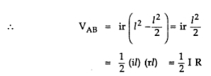
       Thus the voltage drop upto point B can be calculated by putting x =  l .

       where        I = Total current fed at point A
                        R = Total resistance of the distributor
       From this one important observation can be noted as :
       In a uniformly distributed load on the distributor fed at one end, the total voltage drop is equal to that produced by the whole of the load assumed to be concentrated at the middle point. This fact can be used to simplify the complicated load calculations.
       The Fig. 3 shows current loading and voltage drop diagrams.
Fig. 3  Current loading and voltage drop diagram

       The power loss i.e. I2R loss can be obtained from the elementary length dx.
       The current at any point C at distance x is i (l -x). Hence the power loss over the elementary length dx is,

1.2 Distributed Load Fed at Both Ends
       This is type is further classified as,
1. Ends maintained at equal voltages.
2. Ends maintained at unequal voltages.
1.2.1 Ends at Equal Voltages
      The Fig. 4 shows a distributor of length l  with uniform load of i amperes per meter. The resistance of the conductor is r ohms per metre. It is fed at the points A and B which are maintained at equal voltages.
Fig. 4
       The total current to be supplied is i amperes.
       As two end voltages are equal. each end will supply half the required current i.e. i /2.
       The point of minimum potential will be at a distance of /2 from either end i.e. midpoint.
       Consider a point C at a distance x metres from feeding end A as shown in the Fig. 5.
Fig. 5

       The current entering at feeding end A is (i /2).
       Hence the current at point C can be written as,

       Consider an elementary length dx near C whose resistance is rdx.
       So voltage drop over length dx is,

      Hence voltage drop upto point C is,

       Now maximum voltage drop is at midpoint i.e. x = /2 as the midpoint is the point of minimum potential.

       where I is total current and R is the total resistance.
        It is 1/4 th of the drop in case of distributed load distributor fed at one end. The point of minimum potential is the farthest end from feeding end in case of distributor fed at one end while in this case, it is midpoint of the length of the distributor.
Fig. 6  Current loading and voltage drop diagram

       The Fig. 6 shows current loading and voltage drop diagrams.
       The power loss in this case also can be obtained from the power loss over elementary length dx.

      This is power loss over the entire length l  of the distributor. Hence power loss in half length is half of the total power loss which is (i2)/24 watts.
1.2.2  Ends at Unequal Voltages
        The Fig. 7 shows the uniformly distributed load on the distributor of length  . The load is i amperes/m while the distributor is fed at both the ends which are maintained at different voltages.
Fig. 7

       To find the location of point of minimum potential :
       Let point C be the point of minimum potential which is at a distance x from feeding point A.
       The current supplied by the feeding point A is ix. While the current supplied by the feeding point B is i ( - x).
       Now, V1 - drop in section AC = V2 - drop in section BC.
        Let r be the resistance per metre length.
        In case of distributed load the drop is given by ( i  2/2 for a length of ' '. Considering section AC as separate section fed at one end the drop in section AC can be written as,

        Knowing V1V2, i, r and  , the above equation can be solved for x which gives the point of minimum potential.

Read solved examples

Saturday, 2 February 2013

D.C. Distributor With Concentrated Loads


       This distributor is further classified as,
1. Fed at one end.
2. Fed at both the ends.
1.1 Concentrated Loads Fed at One End
       The Fig. 1 shows a distributor with concentrated loads fed at one end A - A'. The loads are connected at the points a - a', b - b' and c - c'.
Let   1,     and    are the lengths of the sections A - a, A - b and A - c respectively. The load currents are I1, I2 and I3. The currents in various sections of the distributor are i1, i and i3.
       From the Fig. 1, applying KCL at various points we can write,
Fig. 1

       The wire A' B' s the return wire of the distributor.
       Let   r' = Resistance per unit length of conductor in Ω
       The various voltage drops can be tabulate as,

       Applying KVL to any loop point voltages can be calculated.
       Now r' is the resistance of single conductor per unit length. And it can be seen that the drops in forward and return conductors are required to be calculated separately and are equal. In practice, the resistance of go and return conductors per unit length is assumed to be r = 2r' and hence two wire distributor can be represented as single wire for calculation purpose, as shown in the Fig. 2.
Now                 r = 2 r'1
                        r = 2r' 
                        r  = 2r' 
Fig. 2 Single wire representation

       And hence all the drop calculations and load point voltages remain same as before.
       The total drop in the distributor is
                        = r i    r i  (     ) + r i  (     2)
       Many times instead of specifying resistances per unit length, actual resistance are specified. The resistance values are of both go and return conductors.
       The current loading and voltage drop diagrams are shown in the Fig. 3.
Fig. 3  Current loading and voltage drop diagrams

       It can be seen that the minimum potential will occur at point c which is farthest from the point A where the distributor is fed at.
1.2 Concentrated Loads Fed at Both End
       This type s further classified depending upon the voltage levels at the two ends.
1. Ends fed with equal voltages 2. Ends fed with unequal voltages.
1.2.1 Ends at Equal Voltages
       The Fig. 4 shows this type of distributor. The ends A and B are maintained at equal voltages.
Fig. 4

       Let r1r2r and r are the go and return resistances of the sections Aa, ab, bc and cB respectively.
       Let point 'b' be the point of minimum potential.
       As we move from point A towards B the potential goes on decreasing and at point b becomes minimum. All the currents between section Ab are supplied by point A. After b the voltage goes on increasing till it becomes feeding voltage at B. All the currents between Bans b are supplied by the point B.
       Now the current at minimum potential point b is supplied by both. Let x be supplied by point A while y be supplied by point B. It is obvious that y =  I - x.
       As both the points A and B are maintained at same voltage, drop in section Aa must be equal to drop in section Bb.
...               i r +  i2  r  =  i3  r +  i r
...               (I1 + x) r1 + x r   = (I - x) r + (I+ I - x) r
       Thus knowing all the currents, x can be calculated and all the voltage drops can be obtained.
       The Fig. 5 shows the current loading and voltage drop diagrams.
Fig. 5 Current loading and voltage drop diagrams

       The load point where the currents are coming from both the sides of the distributor is the point of minimum potential.
1.2.2 Ends at Unequal Voltages
       The Fig. 6 shows this type of distributor. The end s A and B are maintained at different voltages.
Fig. 6

       Let the resistances of the sections Aa, ab, and cB are r1,  r2,  r and r respectively. Let point 'b' is the point of minimum potential.
       In this case also the point b is fed by both the points A and B. The current from point A is x while B it is I2 - x. Now we can write the equation as,
       Voltage drop between A and B = Voltage drop over AB.
       If voltage of A is is V1 and is greater than voltage of B which is V2 then,
       V1 - V2  = drops in all the sections of AB
       The same equation can be written as,
       V1 - drops over Ab = V2 - drops over Bb
       Vi r -  i2  r = V2 - i3  r - i r
       V - (I+ x) r1 - xr  = V2 - (x  - x) r - (I+ I-x) r
       Solving this equation, as v1 and v2 are known, x can be obtained.
       The Fig. 7 shows the current loading and voltage drop diagrams.
Fig. 7 Current loading and voltage drop diagrams


Read Example on dc distributor with concentrated loads