Saturday, 11 October 2014
Video: Electrical Design (Capacitors)
If you take two oppositely charged parallel plates (one set to +Q and the other set to −Q) that are fixed some distance apart, a potential forms between the two. If the two plates are electrically joined by means of a wire, current will flow from the positive plate through the wire to the negative plate until the two plates reach equilibrium (both become neutral in charge). The amount of charge separation that accumulates on the plates is referred to as the capacitance. Devices especially designed to separate charges are called capacitors.
Size: 163 mb
Video: Electrical Design (Ampacity)
Ampacity is a portmanteau for ampere capacity defined by National Electrical Safety Codes, in some North American countries. Ampacity is defined as the maximum amount of electrical current a conductor or device can carry before sustaining immediate or progressive deterioration. Also described as current rating or current-carrying capacity, ampacity is the RMS electric current which a device or conductor can continuously carry while remaining within its temperature rating. (wiki)
Size: 160 mb
Friday, 10 October 2014
Thermocouple Instruments Part1
thermocouple instruments are based on the seebeck effect which states that if the two dissimilar metals having different work functions are joined together to form a junction and if the junction is subjected to change in temperature then voltage is generated at the junction. Such a junction is called thermocouple. The e.m.f. generated is proportional to the temperature difference and is called thermo-electric e.m.f.
The essential elements of a thermocouple instruments are,
1. The heater element : This is nothing but a fine wire which carries the current to be measured. The heater wire is made up of an alloy which has almost zero temperature coefficient of resistance.
2. Thermocouple : This is a junction of two dissimilar metals such as iron and copper-nickel alloy. Its junction is in thermal contact with the heater elements and gets subjected to rise in temperature due to heat produced by the current to be measured. The e.m.f. is available at the output of thermocouple.
3. PMMC Instrument : A sensitive permanent magnet moving coil instrument is necessary to sense the e.m.f. generated at the junction. The deflection of this instrument is proportional to the thermo-electric e.m.f.
The arrangement of thermocouple instrument is shown in the Fig. 1.
 |
| Fig. 1 Basic arrangement of thermocouple instrument |
The e.m.f. produced is proportional to heat i.e. r.m.s. value of the current to be measured. Thus scale of the PMMC instrument can be calibrated to read the current to be measured. The combination of heater element alongwith thermocouple is called thermo-element.
1.1 Principle of Operation
The thermoelectric e.m.f. generated in a thermocouple is proportional to the difference of temperatures of hot and cold junctions. This relation is parabolic in nature and given by,

where a, b = constants depending o metals
T1 - T2 = Temperature difference of hot and cold junctionsLet Δt = T1 - T2 = Difference in temperatures

The equation (2) shows that thermo-electric e.m.f. e has a parabolic relationship with the temperature difference Δt. The constant a is of the order of 40 to 50 μv per oC difference of temperature. The constant b is of the order of few tenths or hundredths of a micorvolt per (oC)2.
The heater element carries the current to be measured and heat produced is proportional to square of the r.m.s. value of the current. Thus the rise in temperature of hot junction is proportional to I2R where I is the r.m.s. value of the current and R is the resistance of the heater element.
If the cold junction is maintained at ambient temperature then the rise in temperature of hot junction is equal to temperature rise of hot junction above the ambient temperature.

Note : The equation (3) shows that thermocouple instruments show the square low response.
Practically the value of constant b is very small and can be neglected.
This e.m.f. drives the PMMC instrument to cause the deflection proportional to e.m.f. e.

where K3 = K1 K2 a R = constant
The above square law is practically not exact as,
1. The heater resistance R is not constant but varies with temperature due to positive or negative temperature coefficient of the heater element. Hence constant K3 is not exactly constant.
2. Practically e.m.f. varies as Δt2 and not only Δt. But the effects of above are not significant and thus if air gap field of PMMC instrument is uniform, the scale can be calibrated interms of I2.
Friday, 3 October 2014
Hot Wire Instruments
The hot wire instruments are based on the principle that length of wire increases due to heating effect when a current passed through it. It is a square law device with a non-linear relationship because increase in length of a wire is directly proportional to the square of current passing through wire. Note that the increase in the length of a wire is very small percentage of the total length of wire. Hence various mechanical linkages have been devised to expand this effect and convert it into motion of a point of a circular scale.
1.1 Construction and Operation of Hot Wire Instrument
The constructional details of a hot-wire double sag type instruments are as shown in the Fig. 1.

A hot working wire denoted by W in the Fig.1 is made up of platinum-irridum alloy. The main advantages of using platinum-irridum alloy is that it can withstand high temperatures without deterioration of wire material caused by oxidation. The working wire W is very fine and its diameter is of the order of 0.1 mm. The wire W is stretched between two point A and B where point B is fixed point and point A is tension adjustment point at which tension adjustment mechanism is placed. One more wire W1, made up of phosphor-bronze is connected to main hot wire W at point C while other end of wire W1 is connected to fixed point D. A fine thread of silk material represented by G is connected between spring S and point F. The thread G is wound around a pulley denoted by E. Both points F and spring S are fixed points. A point P used for indication and thin aluminium disc L are mounted on the spindle. The pulley system E is also mounted on the spindle.
When a current to be measured is passed through the wire, it gets expanded as a result of heating effect by current flowing through it. Because of heating effect, a sag is produced in the wire W. Now the sag in main working wire W causes sag in other wire W1. This sag is transferred to the spring S through a fine silk thread G. Thus the sag produced gets magnified and the spring activates pulley to rotate and pointer gets deflected indicating value of the current under measurement on a graduated scale.
The expansion of the wire is proportional to the heating effect of the current. As heat produced is in the form of power dissipated give P = I2R , the expansion of the wire in hot wire instrument is proportional to the square of r.m.s. value of the current. A thin aluminium disc L rotates between poles of the permanent magnet M and it provides eddy current damping to the instrument. The base of the main instrument is made up of a material which is having coefficient of expansion same as that of hot wire. As base and hot wire, both have same coefficient of expansion, the errors due to uneven expansion between base of instrument and hot wire are minimized.
In early hot wire instruments, the hot wire used was made up of platinum-silver alloy. But the main drawback of early instruments was the low value of the full-scale operating temperature ( about 135-150 oC). Because of very low operating temperature, even small variations in room temperature affects the position of the pointer. Today's hot wire instruments use wire made up of platinum-irridum alloy with which operating temperature range can be extended upto 300 to 500 oC. As the temperature range is increased, the effects due to room temperature variations are minimized. The hot wire is made very thin so that it can attain steady temperature quickly when current flows through wire. The size of wire is decided such that it can bare normal mechanical stresses developed in the instruments.
The hot wire instrument can be used as ammeter over a range 0 to 1 A without a shunt, while 0 to 5 A with a shunt. It can be used as a voltmeter to measure voltage upto 400 V by using high value non-inductive resistance in series with instruments.
1.2 Derivation of Magnification Factor Let us assume that the length of the hot wire be l.
 |
| Fig.1 Sag in main hot wire W |
Let the increase in wire length due to the heating effect by current I to be measured be δl. The sag in the wire due to expansion is given by,
But δl is fractional value and its square value is smaller than itself. Hence neglecting &l term, the sag in wire is given by,

But δl is fractional value and its square value is smaller than itself. Hence neglecting δ2l term, the sag in wire is given by,


To achieve further magnification, a phosphor-bronze wire of length L1is connected at the center of wire W stretched between points A and B as shown in the Fig.2.
 |
| Fig.2 Arrangement of extending magnification |
Let the sag in new wire be S1and it is given by,

Now S is also a fractional value so neglecting higher order term is S i.e. S2, we get,
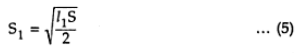

Thus the magnification factor is given by,

1.3 Advantages
The advantages of hot wire instruments are as follows:
1.In hot wire instruments, the deflection of instrument is measured in terms of the r.m.s. current flowing through the wire irrespective of its frequency or waveform. Thus it can be used in a.v. as well as d.c. systems. The reading of the instrument is independent of frequency and waveform of the current to be measured.
2. The operation is not based on any magnetic effect, hence the instrument is free from stray magnetic field.
3. In a.c. as well as d.c. systems, the calibration is not different.4. The error due to temperature variations are not much significant. with suitable adjustments these errors can be eliminated.
5. This instrument can be used for current measurements at very high frequencies.
6. It is fairly accurate instrument.7. Its construction is very simple and it is cheaper.
1.4 Disadvantages
The disadvantages of hot wire instruments are as follows.
1. The instrument is not able to withstand overloads because wire is so fine and it may melt before any protection circuit operates.
2. Similar to moving iron type instruments, its scale is uneven.
3. It consumes verly high power.4. The instrument is delicate.
5. As the time is elasped in heating working wire, the response of the instrument is slow.
6. Due to temperature variations in the surroundings, it is necessary to adjust zero position frequently.
7. The instrument does not provide same deflection for ascending and descending values.