Principle of Automatic Voltage Regulator
Automatic Voltage Regulator (AVR):
Automatic Voltage Regulator is a device which maintains the Generator output terminal voltage. To be more accurate, AVR is a controller which always compares the Generator output terminal voltage Vt with the set reference voltage Vrefand as per the error signal i.e. (Vref - Vt) it changes the filed excitation of Generator to maintain constant terminal voltage Vt.Principle of Automatic Voltage Regulator:
For better understanding of principle of Automatic Voltage Regulator i.e. AVR, we will first have a brief look on Generator Excitation System. I am here taking static excitation system for example. As we know that in static excitation system Generator output is fed to a thyristor bridge rectifier. This thyristor bridge rectifier converts the AC current to DC current. Note that the DC current output by the Thyristor Bridge can be controlled by controlling the firing angle of the Thyristor. The DC current output of Thyristor Bridge is then fed to the filed winding of Generator as shown in figure below.
Let us assume that filed current at any time is If. Then the air gap flux of Generator may be written as � = KIf where K is some constant.
But we are interested in maintaining the Generator Output Terminal Voltage Vt which is given as
Vt = 1.414pfN� where symbols have their usual meaning.
From the above, it is quite obvious that changing If will change the terminal voltage Vt.
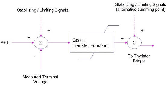
Thus voltage regulation can be achieved by controlling field current. Automatic Voltage Regulator AVR performs this action by changing its firing angle. Figure below shows a simplified diagram of AVR.
AVR takes three inputs namely reference voltage Vref, terminal voltage Vt and limiting signals. For simplicity we will assume only two inputs Vref and Vt. Reference voltage Vref is manually set in AVR. This reference voltage is also dynamically changed around the manually set Vref by Power System Stabilizer (PSS). But for this discussion we will eliminate the effect of PSS and assume that Vref is constant. The Error Signal (Vref-Vt) is fed to Controller. The controller in the diagram is denoted by its Transfer Function. The output of Transfer Function is the fed to Thyristor Bridge Rectifier to change firing angle and hence field excitation.
Suppose Vref = 21 kV and due to some reason the terminal voltage Vt = 25 kV. Thus AVR will reduce the field current If to reduce the value of air gap flux. This in turn will reduce the terminal voltage and will try to make it stable at 21 kV.
Principle of Automatic Voltage Regulator
 Reviewed by haru
on
September 21, 2017
Rating:
 Reviewed by haru
on
September 21, 2017
Rating:


No comments