
Optical Fiber Waveguides
. In free space light travels at its maximum possible speed i.e. 3x10⁸ m/s or 186x103 miles/sec. when light travels through a material it exhibits certain behavior explained by laws of reflection, refraction.
1. Electromagnetic Spectrum
. The radio waves and light are electromagnetic waves. The rate at which they alternate in polarity is called their frequency (f) measured in hertz (Hz). The speed of electromagnetic wave (c) in free space approximately 3x10⁸ m/sec. the distance travelled during each cycle is called as wavelength (λ).

. In fiber optics, it is more convenient to use the wavelength of light instead of the frequency with light frequencies, wavelength is often stated in microns or nanometers.
1 micron (μ) = 1 micometre (1 x 10⁻⁶)
1 nano (n) = 10-9 metre
Fig. 1 shows electromagnetic frequency spectrum.


. Fiber optics uses visible and infrared light. Infrared light covers a fairly wide range of wavelengths and is generally used for all fiber optic communications. Visible light is normally used for very short range transmission using a plastic fiber.
2. Ray Transmission Theory
. Before studying how the light actually propagates through the fiber, laws governing the nature of light must be studied. These are called as laws of optics (Ray theory). There is conception that light always travels at the same speed. This fact is simple not true. The speed of light depends upon the material or medium though which it is moving. In free space light travels at its maximum possible speed i.e. 3x10⁸ m/s or 186x103 miles/sec. when light travels through a material it exhibits certain behavior explained by laws of reflection. Refraction.
2.1 Reflaction
. The law of reflection states that, when a light ray is incident upon a reflective surface at some incident angle Φ1 from imaginary perpendicular normal, the ray will be reflected from the surface at some angle Φ2 from normal which is equal to the angle of incidence.
Fig. 2 shows law of reflection.

2.2 Refraction
. Refraction occurs when light ray passes from on medium to another i.e. the light ray changes its direction at interface. Refraction occurs whenever density of medium changes e.g. refraction occurs at air and water interface the straw in a glass of water will appear as it is bent.
The refraction can also be observed at air and glass interface.
. When wave passes through less dense medium to more dense medium, the wave is refracted (bent) towards the normal Fig. 3 shows the refraction phenomena.
. The refraction (bending) takes place because light travels at different speed in different mediums. The speed of light in free space is higher than in water or glass.

2.3 Refractive Index
. The amount of refraction or bending that occurs at the interface of two materials of different densities is usually expressed as refractive index of two materials. Refractive index is also known as index of refraction and is denoted by n.
. Based on material density, the refractive index is expressed as the ratio of the velocity of light in free space to the velocity of light of the dielectric materials (substance).

The refractive index for vacuum and air is 1.0 for water it is 1.3 and for glass refractive index is 1.5.
2.4 Snell's Law
. Snell's law states how light ray reacts when it meets the interface of two media having different indexes of refraction.
. Let the two medias have refractive indexes n1 and n2 where n1 ˃ n2. Φ1 and Φ2 be the angles of incidence and angle of refraction respectively. Then according to Snell's law, a relationship exists between the refractive index of both materials given by,

. A refractive index model for Snell's law is shown in Fig. 4

. The refracted wave will be towards the normal when n n and will away from it when n1 ˃ n2.
Equations (1) can be written as,

.This equation shows that the ratio of refractive index of two mediums is inversely proportional to the refractive and incidence angles.
As refractive index n = c/V1 and n = c/V2 substituting these values in equation (2).

2.5 Critical Angle
. When the angle of incidence (Φ1) is progressively increased, there will be progressive increase of refractive angle (Φ2). At some condition (Φ1) the refractive angle (Φ2) becomes 90° to the normal. When this happens the refracted light ray travels along the interface. The angle of incidence (Φ1) at the point at which the refractive angle (Φ2) becomes 90° is called the critical angle. It is denoted by Φc.
. The critical angle is defined as the minimum angle of incidence (Φ1) at which the ray strikes the interface of two media and causes an angles of refraction (Φ2) equal to 90°. Fig. 5 shows critical angle refraction.

Hence at critical angle Φ1= Φc and Φ2 = 90°
Using Snell's law : n1 sinΦ1 = n2 sinΦ2

. The actual value of critical angle is dependent upon combination of materials present on each side of boundary.
2.6 Total Internal Reflection (TIR)
. When the incident angle is increased beyond the critical angle, the light ray does not pass through the interface into the other medium. This gives the effect of mirror exist at the interface with no possibility of light escaping outside the medium. In this condition angle of reflection (Φ2) is equal to angle of incidence (Φ1). This action is called as Total Internal Reflection (TIR) of the beam. It is TIR that leads to the propagation of waves within fiber-cable medium. TIR can be observed only on materials in which the velocity of light is less than in air.
. The two conditions necessary for TIR to occur are :
1.The refractive index of first medium must be greater than the refractive index of second one.
2. The angle of incidence must be greater than (or equal to) the critical angle.


since critical angle θc is less than angle of incidence Φ1 but for total internal reflection (TIR) to exist the incident angle (Φ1) must be greater than critical angle (θc). in the given problem Φ1= 80° and θc =71°, hence TIR will take place
3. Optical Fiber as Waveguide. An optical fiber is a cylindrical dielectric waveguide capable of conveying electromagnetic waves at optical frequencies. The electromagnetic energy is in the form of the light and propagates along the axis of the fiber. The structural of the fiber determines the transmission characteristics.
. The propagation of light along the waveguide is decided by the modes of the waveguides, here mode means path. Each mode has distict pattern of electric and magnetic field distributions along the fiber length. Only few modes can satisfy the homogeneous wave equation in the fiber also the boundary condition at waveguide surfaces. When there is only one path for light to follow then it is called as single mode propagation. When there is more than one path then it is called as multimode propagation.
Single fiber structure
. A single fiber structure is shown in Fig. 6 it consists of a solid dielectric cylinder with radius 'a'. this cylinder is called as core of fiber. The core is surrounded by dielectric, called cladding. The index of refraction of core (glass fiber) is slightly greater than the index of refraction of cladding.
If refractive index of core (glass fiber) = n1
and refractive index of cladding = n2
then n1 ˃ n2.

4. Propagation in Optical Fiber
. To understand the general nature of light wave propagation in optical. We first consider the construction of optical fiber. The innermost is the glass core of very thin diameter with refractive index of n1. the glass core is surrounded by a cladding material with a slight lower refractive index n2.The light wave can propagate along such a optical fiber. A single mode propagation is illustrated in Fig. 7 along with standard size of fiber.

. Single mode fibers are capable of carrying only one signal of a specific wavelength.
. In multimode propagation the light propagates along the fiber in zigzag fashion, provided it can undergo total internal reflection (TIR) at the core cladding boundaries.
. Total internal reflection at the fiber wall can occur only if two conditions are satisfied.
Condition 1 :
The index of refraction of glass fiber must be slightly greater than the index of refraction of material surrounding the fiber (cladding).
If refractive index of glass fiber = n1
and refractive index of cladding = n2
then n1 ˃ n2.
Condition 2 :
The angle incidence (Φ1) of light ray must be greater than critical angle (Φc).
. A light beam is focused at one end of cable. The light enters the fibers at different angles. Fig. 8 shows the condition exist at the launching end of optic fiber. The light source is surrounded by air and the refractive index of air is n0 =1. Let the incident ray makes an angle Φ0 with fiber axis. The ray enters into glass fiber at point P making refracted angle Φ1 to the fiber axis. , the ray is then propagated diagonally down the core and reflect from the core wall at point Q. when the light ray reflects off the inner surface, the angle of incidence is equal to the angle reflection, which is greater than critical angle.
. In order for a ray of light to propagate down the cable, it must strike the core cladding interface at an angle that is greater than critical angle (Φc).

4.1 Acceptance Angle
Applying Snell's law to external incidence angle.

Substituting sinΦ1 in above equation

Applying Pythagorean theorem to ΔPQR.


The maximum value of external incidence angle for which light will propagate in the fiber.

When the light rays enters the fibers from an air medium n0 = 1. Then above equation reduces to,

The angle Φ0 is called as acceptance angle and Φ0(max) defines the maximum angle in which the light ray may incident on fiber to propagate down the fiber.
4.2 Acceptance Cone
. Rotating the acceptance angle Φ0(max) around the fiber axis, a cone shaped pattern is obtained, it is called as acceptance cone of the fiber input. Fig. 10 shows formation of acceptance cone of a fiber cable.

. The cone of acceptance is the angle within which the light is accepted into the core and is able to travel along the fiber. The launching of light wave becomes easier for large acceptance cone.
. The angle is measured from the axis of the positive cone so the total angle of convergence is actually twice the stated value.
4.3 Numerical Aperture (NA)
. The numerical aperture (NA) of a fiber is a figure of merit which represents its light gathering capability. Larger the numerical aperture, the greater the amount of light accepted by fiber. The acceptance angle also determines how much light is able to be enter the fiber and hence there is relation between the numerical aperture and the cone of acceptance.
Numerical aperture (NA) = sin Φ0(max)

Hence acceptance angle = sin-1 NA
By the formula of NA note the numerical aperture is effectively dependent only on refractive indices of core and cladding material. NA is not a function of fiber dimension.
. The index difference (Δ) and the numerical aperture (NA) are related to the core and cladding indices :


5. Types of Rays
. If the rays are launched within core of acceptance can be successfully propagated along the fiber. But the exact path of the ray is determined by the position and angle of ray at which it strikes the core.There exists three difference types of rays.
i) Skew rays ii) Meridional rays iii) Axial rays.
.The skew rays does not pass through the center, as shown in Fig. 11 (a). the skew rays reflects off from the core cladding boundaries and again bounces around the outside of the core. It takes somewhat similar shape of spiral or helical path.

.The meridional ray enters the core and passes through its axis. When the core surface is parallel, it will always be reflected to pass through the enter.The meridional ray is shown in Fig. 11 (b).
.The axial ray travels along the axis of the fiber and stays at the axis all the time. It is shown in Fig. 11 (c).
6. Modes of Fiber
. Fiber cables can also be classified as per their mode. Light rays propagate as an electromagnetic wave along the fiber. The two components, the electric field and the magnetic field from patterns across the fiber. These patterns are called modes of transmission. The mode of a fiber refers to the number of paths for the light rays within the cable. According to modes optic fibers can be classified into two types.
i) Single mode fiber ii) Multimode fiber.
. Multimode fiber was the first fiber type to be manufactured and commercialized. The term multimode simply refers to the fact that numerous modes (light rays) are carried simultaneously through the waveguide. Multimode fiber has a much larger diameter, compared to single mode fiber, this allows large number of modes.
. Single mode fiber allows propagation of light ray by only one path. Single mode fibers are best at retaining the fidelity of each light pulse over longer distance also they do not exhibit dispersion caused by multiple modes.Thus more information can be transmitted per unit of time.This gives single mode fiber higher bandwidth compared to multimode fiber.
. Some disadvantages of single mode fiber are smaller core diameter makes coupling light into the core more difficult. Precision required for single mode connectors and splices are more demanding.
7. Fiber Profiles
. A fiber is characterized by its profile and by its core and cladding diameters.
. One way of classifying the fiber cables is according to the index profile at fiber. The index profile is a graphical representation of value of refractive index across the core diameter.
. There are two basic types of index profiles.
i) Step index fiber. ii) Graded index fiber.
Fig. 12 shows the index profiles of fibers.

7.1 Step Index (SI) Fiber
.The step index (SI) fiber is a cylindrical waveguide core with central or inner core has a uniform refractive index of n1 and the core is surrounded by outer cladding with uniform refractive index of n2. the cladding refractive index (n2) is less than the core refractive index (n1). but there is an abrupt change in the refractive index at the core cladding interface. Refractive index profile of step indexed optical fiber is shown in Fig. 13 the refractive index is plotted on horizontal axis and radial distance from the core is plotted on vertical axis.

. The propagation of light wave within the core of step index fiber takes the path of meridional ray i.e. ray follows a zig-zag path of straight line segments.
The core typically has diameter 50-80 m and the cladding has a diameter of 125 µm.
.The refractive index profile is defined as-

7.2 Graded Index (GRIN) Fiber
. The graded index fiber has a core made from many layers of glass.
.In the graded index (GRIN) fiber the refractive index is not uniform within the core, it is highest at the centre and decreases smoothly and continuously with distance towards the cladding. The refractive index across the core takes the parabolic nature. Fig. 14 shows refractive index profile of graded index fiber.

. In graded index fiber the light waves are bent by refraction towards the core axis and they follow the curves path down the fiber length. This results because of change in refractive index as moved away from the center of the core.
. A graded index fiber has lower coupling efficiency and higher bandwidth than the step index fiber. It is available in 50/125 and 62.5/125 sizes. The 50/125 fiber has been optimized for long haul applications and has a smaller NA and higher bandwidth.62.5/125 fiber is optimized for LAN applications which is costing 25% more than the 50/125 fiber cable.
. The refractive index variation in the core is given by relationship
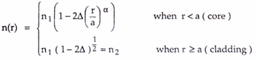
Where,
r = Radial distance from fiber axisA
a = Core radiusN
n1 = Refractive index of core
n2 = Refractive index of cladding
α = Shape of index profile.
. Profile parameter α determines the characteristics refractive index profile of fiber core. The range of refractive index as variation of is shown in Fig. 15

7.3 Comparison of Step Index and Graded Index Fiber

7.3 Comparison of Step Index and Graded Index Fiber
8. Optical Fiber Configurations
.Depending on the refractive index profile of fiber and modes of fiber there exist three types of optical fiber configurations. There optic-fiber configurations are –
i) Single mode step index fiber.
ii) Multimode step index fiber.
iii) Multimode graded index fiber.
8.1 Single Mode Step Index Fiber
. In single mode step index fiber has a central core that is sufficiently small so that there is essentially only one path for light ray through the cable. The light ray is propagated in the fiber through reflections. Typically core sizes are 2 to 15 µm. single mode fiber is also known as fundamental or monomode fiber.
Fig. 16 shows single mode fiber.

. Single mode fiber will permit only one mode to propagate and does not suffer from mode delay difference. These are primarily developed for the 1300 nm window but they can be also be used effectively with time division multiples (TDM) and wavelength division multiplex (WDM) systems operating in 1550 nm wavelength region.
. The core fiber of a single mode fiber is very narrow compared to the wavelength of light being used. Therefore, only a single path exists through the cable core through which light can travel. Usually, 20 percent of the light in a single mode cable actually travels down the cladding and the effective diameter of the cable is a blend of single mode core and degree to which the cladding carries light. This is referred to as the mode field diameter, which is larger than physical diameter of the core depending on the refractive indices of the core and cladding.
. The disadvantage of this type of cable is that because of extremely small size interconnection of cables and interfacing with source is difficult. Another disadvantage of single mode fibers is that as the refractive index of glass decreases with optical wavelength, the light velocity will also be wavelength dependent. Thus the light from an optical transmitter will have definite spectral width.
8.2 Multimode Step Index Fiber
. Multimode step index fiber is most widely used type. It is easy to manufacture. Its core diameter is 50 to 1000 µm i.e. large aperture and allows more light to enter the cable. The light rays are propagated down the core in zig-zag manner. There are many many paths that a light ray may follow during the propagation.
. The light ray is propagated using the principle of total internal reflection (TIR). Since the core index of refraction is higher than the cladding index of refraction, the light enters at less than critical angle is guided along the fiber.

. Light rays passing through the fiber are continuously reflected off the glass cladding towards the centre of the core at different angles and lengths, limiting overall bandwidth.
. The disadvantage of multimode step index fibers is that the difference optical lengths caused by various angles at which light is propagated relative to the core, causes the transmission bandwidth to be fairly small. Because of these limitations, multimode step index fiber is typically only used in applications requiring distances of less than 1 km.
8.3 Multimode Graded Index Fiber
. The core size of multimode graded index fiber cable is varying from 50 to 100 µm range. The light ray is propagated through the refraction. The light ray enters the fiber at many different angles. As the light propagates across the core toward the center it is intersecting a less dense to more dense medium. Therefore the light rays are being constantly being refracted and ray is bending continuously. This cable is mostly used for long distance communication.
Fig. 18 shows multimode graded index fiber.

. The light rays no longer follow straight lines, they follow a serpentine path being gradually bent back towards the center by the continuously declining refractive index. The modes travelling in a straight line are in a higher refractive index so they travel slower than the serpentine modes. This reduces the arrival time disparity because all modes arrive at about the same time.
. Fig. 19 shows the light trajectory in detail. It is seen that light rays running close to the fiber axis with shorter path length, will have lower velocity because they pass through a region with a high refractive index.

. Rays on core edges offers reduced refractive index, hence travel more faster than axial rays and cause the light components to take same amount of time to travel the length of fiber, thus minimizing dispersion losses. Each path at a different angle is termed as transmission mode and NA of graded index fiber is defined as the maximum value of acceptance angle at the fiber axis.
.Typical attenuation coefficient of graded index fibers at 850 nm are 2.5 to 3 dB/km, while at 1300 nm they are 1.0 to 1.5 dB/km.
. The main advantages of graded index fiber are:
1. Reduced refractive index at the centre of core.
2. Comparatively cheap to produce

Optical Fiber Waveguides
 Reviewed by haru
on
February 23, 2018
Rating:
Reviewed by haru
on
February 23, 2018
Rating:
Reviewed by haru
on
February 23, 2018
Rating:


No comments