
LED
The LED is an optical diode, which emits light when forward biased. The Fig. 1 shows the symbol of LED which is similar to p-n junction diode apart from the two arrows indicating that the device emits the light energy.

1. Basic Operation
Whenever a p-n junction is forward biased, the electrons across the p-n junction from the n type semiconductor material and recombine with the holes in p type semiconductor material. The free electrons are in the conduction band while the holes are present in the valence band. Thus the free electrons are at higher energy level with respect to the holes. When a free electron recombines with hole, it falls from conduction band to a valence band. Thus the energy level associated with it changes from higher value to lower value. The energy corresponding to the different between higher level and lower level is released by an electron while travelling from the conduction band to the valence band. In normaldiodes, this energy released is in the form of heat. But LED is made up some special material which release this energy in the form of photons which emit the light energy. Hence such diodes are called light emitting diodes.
This process is called electrominescence.
The Fig. 2 shows the basic principle of this process. The energy released in the form of light depends on the energy corresponding to the forbidden gap. This determines the wavelength of the emitted light. The wavelength determines the colour of the light and also determines whether the light is visible or invisible (infrared). The various impurities are added during the doping process to control the wavelength and colour of the emitted light. For normal silicon diode, the forbidden energy gap is 1.1 eV and wavelength of the emitted light energy corresponds to that of infrared light spectrum hence in normal diodes the light is not visible. The infrared light is not visible.

2. Materials used in LEDs
The LEDs use the materials like gallium arsenide (GaAs), gallium arsenide phosphide (GaAsP) or gallium, arsenic and phosphorus. GaAs LEDs emit light radiations which are infrared hence invisible. GaAsP produces red or yellow visible while GaP emits red or green visible light. Some LEDs emit blue and orange light too.

3. Construction of LED
One of the methods used for the LED construction is to deposite three semiconductor layers on the substrate as shown in the Fig. 3. In between p type and n type, there exists and active region. This active region emits light, when electron and hole recombine. When the diode is forward biased, holes from p type and electrons from n type, both get driven into the active region. And when recombine, the light is emitted.

In this particular structure, the LED emit light all the way around the layered structure. Thus the basic layered structure is placed in a tiny reflective cup so that the light from the active layer will be reflected towards the desired exit direction. This is shown in the Fig. 4(a) while the symbol of LED indicating identification of anode and cathode is shown in the Fig. 4(b).

4. LED : Voltage and Current
Consider a source connected to LED and a resistor as shown in the Fig 5.

The outward arrows associated with a diode indicate that it is LED.
The resistor RS is the current limiting resistor. Due to this resistor, the current through the circuit is limited and prevented from exceeding the maximum current rating of the diode.
Let VS = supply voltage
VD = drop across LED
Applying KVL to the circuit we can write,

When forward biased, the voltage drop across conducting LED is about 2 to 3 V which is considerably greater than that across a normal silicon or germanium diode. The current range of commercially available LEDs is 10 to 80 mA. Unless and otherwise specified, while analyzing the LED circuits, the drop across LED is considered as VD = 2V.
The reverse breakdown voltage of LED is much less than the normal diode, which is about 3 V to 10V.
5. Spectral Output Curves for LED
The visibility of the light is decided from its wavelength (λ). The graph output light of LED against the wavelength λ gives the various curves called spectral output curves for LEDs. These are shown in the Fig 6.

It can be seen that wavelength is expressed in nm (nanometers). The normalized output for visible light shows peak at 460 nm for blue, at 450 nm for green, at 590 nm for yellow and at 660 nm for red. The infrared invisible light output shows a peak at 940 nm.
6. Radiation Pattern of LED
LED is a directional light source. It emits the light in a particular way which has a typical radiation pattern. Maximum emitted power is perpendicular to the emitting surface. The Fig 7. shows a radiation pattern for a typical LED, which shows that most of the energy is emitted within 20° of the direction of maximum light.
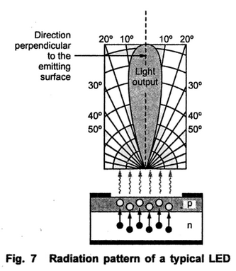
Some LEDs use plastic lenses to spread the light for a greater angle to increase the visibility. The coloured lenses are also used to enhance the colour.
7. Output Characteristics of LED
The amount of power output translated into light is directly proportional to the forward current If. More the forward current If, the greater is the output light. The graph of forward current and output light in mW is shown in the Fig. 8. This is called output characteristics for LED.

when forward biased, the voltage drop across conducting LED is about 2 to 3 V which is considerably greater than that across a normal silicon or germanium diode. The current range of commercially available LEDs is 10 to 80 Ma. Unless and otherwise specified, while analyzing the LED circuits, the drop across LED is considered as VD = 2V.
The reverse breakdown voltage of LED is much less than the normal diode, which is about 3 V to 10 V.
8. Data Sheet Information of LED
The two important parameters related to LED characteristics are,
i) Radiant intensity : The LED output power per steradian is called axial radiant intensity. The symbol for radiant intensity is Ie. The steradian (sr) is the unit of solid angle. The unit of radiant intensity is W/sr or mW/sr.
ii) Irradiance : The power per unit area at a given distance from the LED source is called irradiance. It is denoted as H and expressed in W/cm2 or mW/cm2. mathematically irradiance can be calculated as,
H = Ie/d2
where Ie = Radiant intensity
d = distance from LED source in cm
The electrical characteristics, maximum ratings and optical characteristics of a typical MLED81 are given in the following tables.


Similarly the data sheet includes some graphical characteristics. The Fig. 9 shows spatial radiation pattern and intensity versus forward current graphs for MLED 81.
 |
| Fig. 9 MELD 81 data sheet graphs |
The Fig. 10 shows other two graphs for MLED 81 available in its datasheet.

It can be seen for this device that at 30 on the either side of the maximum orientation, the output power reduces to about 60% of the maximum.
9. Advantages of LED
The various advantages of LED are,
1. LEDs are small in size, and hence can be regarded as point source of light. Because of their small size, several thousand LEDs can be packed in one sq. metre area.
2.The brightness of light emitted LED depends on the current flowing though LED. Hence the brightness of light can be smoothly controlled by varying the current. This makes possible to operate LED displays under different ambient lighting conditions.
3. LEDs are fast operating devices. They can be turned on and off in time less than 1 microsecond.
4. The LEDs are light in weight.
5. The LEDs are available in various colours.
6. The LEDs have long life.
7. The LEDs are cheap and readily available.
8. The LEDs are easy to interface with various other electronic circuits.
9. Some LEDs radiate infrared light which is invisible but still useful in some applications like burglar alarm systems.
10. Disadnatges of LED
The various disadvantages of LED are,
1. It draws considerable current requiring frequent replacement of battery in low power battery operated dvices.
2. Luminous efficiency of LEDs is low which is about 1.5 lumen /watt.
3. The characteristics are affected by temperature.
4. Need large power for the operation compared to normal p-n junction diode.
11. Applications of LED
Due to the advantages like low voltage, long life, cheap, reliable, fast on-off switching etc, the LEDs are used in many applications. The various applications of LED are,
1. All kinds of visual displays i.e. seven segment displays and alpha numeric displays. Such displays are commonly used in the watches and calculators.
2. In the optical devices such as optocouplers.
3. As on-off indicator in various types of electronic circuits.
4. Some LEDs radiate infrared light which is invisible. But such LEDs useful in remote controls and applications like burglar alarm.
12. comparison of led and p-n junction diode


12. comparison of led and p-n junction diode
13. Other Applications of LED
The circuits and brief description of some other applications of LED are given below
Another important application area of LED is displays. The LEDs are commonly used in seven segment displays and alpha numeric displays.
LED
 Reviewed by haru
on
February 20, 2018
Rating:
Reviewed by haru
on
February 20, 2018
Rating:
Reviewed by haru
on
February 20, 2018
Rating:


No comments