
Optocoupler
The combined package of a LED and a photodiode is called optocoupler. It is also called an optoisolator or an optically coupled isolator.
The Fig. 1 shows the basic circuit of an optocoupler. It has LED on the input side and a photodiode on the output side.

The source V1 and series resistance R1 decide the forward current I1 through the LED. Thus LED emits the light. This light is incident on a photodiode. Due to this, a reverse current is set up I the output circuit. This current produces a drop across the output resistance R2. The output voltage is the difference between the supply voltage V2 and the drop across the resistors R2.

Now if input voltage is changed, the amount of light emitted by LED changes. This varies the reverse current in the output circuit and hence the output voltage. The output voltage is thus varying in step with the input voltage. This coupling between LED and photodiode is hence called optocoupler. As the name suggests this device can couple an input signal to the output circuit.
Fig. 2(a) shows the typical optoisolator. It consists of LED and phototransistor.

When the input voltage forward biases the LED, light transmitted to the phototransistor turns it on, resulting current through the external load, as shown in Fig. 2(b).
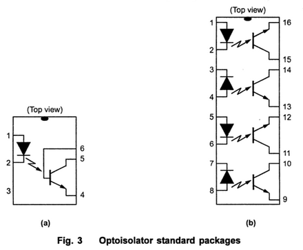
1. Optoisolator Package
The optoisolators are available in standard IC package as shown in Fig. 3.
2. Characteristics of Optocoupler
Following are the important characteristics of an optocoupler :
i) Current transfer ratio
ii) Isolation voltage
iii) Response time
iv) Common mode rejection.
i) Current transfer ratio (CTR) : The current transfer ratio refers to the ratio of the output collector current (IC) to the input forward current (IF).

The CTR greatly differs depending on the type of the phototransistor used in photocoupler. The photocoupler using Darlington phototransistor can provide a relatively large collector current from a small input current. The CTR also varies with ambient temperature.
ii) Isolation voltage between input and output (Viso) : Isolation voltage (Viso) between input and output is another important factor in choosing a photocoupler .this is because photocouplers are often used for signal transmission between circuits that have different potentials or as interfaces with actuator circuits which tend to generate impulsive voltage, such as motor controllers or solenoid driver circuits. Isolation voltage is specified in KVrms with a relative humidity of 40 to 60 %
iii) Response time : The response time of a optocoupler depends mainly on the output phototransistor. The response time also depends on the input forward current and load resistance. Since load resistance has a greater influence on the response time, careful setting is required while defining the circuit constant.
iv) Common mode rejection : While the photocouplers output is electrically isolated from its input for relatively low frequency signal, an impulsive input voltage may cause a displacement current (id = Cf .dv /dt) to flow due to the floating capacitance (Cf) between the input and output of the photocoupler, causing noise voltage to appear at the output.
3. Advantages
1. The electrical isolation between input and output circuit. The coupling between input and output is through the beam of light. There is a transparent insulating cap between the two elements embedded in the design to permit the passage of light. So there exists an insulation resistance of several megaohms between input and output circuit. This type of isolation is useful in high voltage applications where the voltages of the input and output circuits differ by several thousand volts.
2. The response times of optocoupler is so small that they can be used to transmit data in the megahertz range.
3. Capable of wideband signal transmission.
4. Unidirectional signal transfer means that output does not loop back to the input circuit.
5. Easy interfacing with logic devices.
6. Compact and light weight.
7. Much faster than the isolation transformers and relays.
8. As signal transfer is unilateral, changing load do not affect input.
9. The problem such as noise, transients, contact bounce etc. are completely eliminated.Light emitting diode The light emitting diode (LED) converts electric energy to optical energy (light).
Optocoupler
 Reviewed by haru
on
February 09, 2018
Rating:
Reviewed by haru
on
February 09, 2018
Rating:
Reviewed by haru
on
February 09, 2018
Rating:


No comments